FPV Video Transmitter for Inspection Drones: Stable Link
Inspection drone video problems are rarely caused by one single part. Weak signal, snow screen, image jump, black screen, and short disconnection usually show that the link needs a cleaner diagnosis before the VTX power level is selected.
For this reason, a stable fpv video transmitter setup should match the aircraft type, route distance, receiver position, antenna layout, power input, cooling condition, and real inspection environment.
This article focuses on inspection drone use cases such as power-line routes, industrial parks, mountain edges, solar sites, equipment yards, roofs, bridges, and long corridor patrols. It explains how to match 25W, 16W, and 10W VTX options without turning the article into a generic parameter list.
Start from the inspection symptom
In inspection work, the first clue is the image symptom. A snowy image that becomes worse with distance is different from nearby snow at takeoff. Likewise, image jump during a turn is different from sudden black screen during a climb. Therefore, the first step is not to increase power blindly.
Gradual snow usually means the useful RF margin is becoming lower. This can happen in long corridors, open-area patrol, mountain-edge routes, and fixed-wing inspection paths. However, close-range snow often comes from channel mismatch, dirty power, poor grounding, weak connectors, or antenna damage.
Image jump during turns usually points to antenna shadow or angle loss. The battery, landing gear, payload shell, carbon frame, or inspected equipment may block the RF path for a short moment. Therefore, the antenna should be tested on the final aircraft, not only on the bench.
A sudden black screen is more serious. It may come from camera output loss, voltage drop, receiver sync loss, VTX overheating, or a loose connector. Because of this, black screen should never be treated as a simple distance problem.
Quick Navigation
Fast Inspection Troubleshooting Map
| Image symptom | Likely direction | Recommended check |
|---|---|---|
| Snow grows with distance | Low RF margin | Receiver height, antenna direction, route blockage, VTX power class |
| Snow appears nearby | Power noise or channel conflict | Grounding, cable routing, exact channel match, SMA connector |
| Image breaks during turns | Antenna shadow or angle loss | Antenna position, polarization, receiver diversity, airframe blockage |
| Sudden black screen | Power, heat, camera, or connector interruption | Voltage log, heat test, connector vibration check, camera output |
Match the route, not only the wattage
Inspection drones fly in very different signal conditions. A power-line corridor, a factory park, a mountain road, a solar farm, and a rooftop equipment check may all use analog FPV video, but each route stresses the link in a different way.
For line inspection, the aircraft often moves away from the receiving side for a long time. Distance grows gradually, and the route may include towers, poles, wires, trees, slopes, and service roads. In this case, more RF margin can help maintain a usable picture at the far end.
For industrial park inspection, the route may be shorter, but the RF environment can be crowded. WiFi devices, steel structures, electrical equipment, roofs, vehicles, and metal walls can create reflection and noise. Therefore, channel planning, receiver placement, and clean wiring can be more important than raw distance.
For mountain and forest routes, partial blockage is the key issue. Trees, terrain edges, slope changes, and low-altitude passes can reduce line-of-sight quality. As a result, the receiving antenna should be placed higher whenever possible.
For equipment inspection, the drone may stay close to the object, but image value is high. The operator may need to see cable clearance, bolt position, tower edges, surface damage, or safe approach distance. In this case, low latency and stable close-range video help more than a headline range number.
Product matching: 25W, 16W, and 10W for inspection drones
FlyMind’s inspection-oriented VTX path should focus on 25W, 16W, and 10W models. Each power level has a different role. The goal is not to push every route toward the highest number. Instead, the goal is to select enough margin for the route while keeping power input, heat, weight, and mounting practical.
In general, 25W fits demanding long-route inspection. Meanwhile, 16W is a strong middle choice for mixed industrial routes. In addition, 10W is useful for compact inspection drones, controlled site checks, and sample validation before a higher-power rollout.
25W for demanding long-route inspection
The 25W model should be considered when distance pressure is serious. It fits larger UAV platforms, power-line inspection, pipeline patrol, long road corridors, river routes, wide-area industrial monitoring, and open-area missions where far-end image stability matters.
However, 25W needs stricter system design. The aircraft must support stable input power, secure mounting, correct antenna setup, and reliable heat dissipation. Otherwise, higher output may expose weak wiring or poor cooling faster.
 View 25W 5.8GHz long range VTX
16W for mixed industrial inspection environments
The 16W model is useful when the route mixes distance, interference, and structural blockage. It suits factory parks, equipment yards, suburban inspection, rolling hills, light woodland, fixed-wing cruise routes, and long corridor work that does not always require the highest power level.
Moreover, 16W gives more headroom than 10W while keeping integration pressure more manageable than 25W. This makes it a practical middle option for repeated UAV projects, especially where low latency and stable analog response are important.
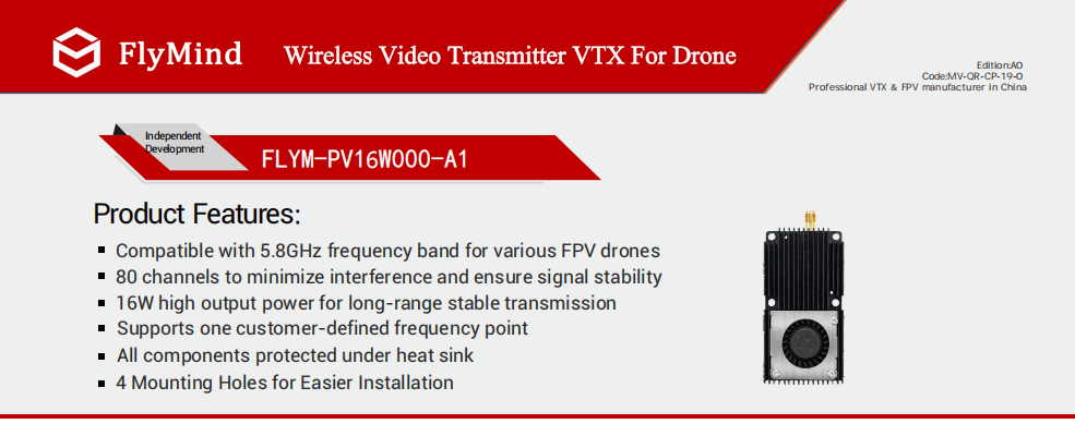 View 5.8GHz 16W low latency VTX
10W for compact inspection drones and validation builds
The 10W model fits compact inspection platforms, short-to-medium site checks, equipment inspection, sample testing, training routes, and controlled validation work. It provides stronger link confidence than small low-power modules while keeping integration practical for tighter airframes.
In addition, 80CH support helps with cleaner channel planning during repeated testing. For early engineering work, 10W can verify camera signal, receiver compatibility, wiring quality, antenna position, and cooling layout before the project scales to 16W or 25W.
 View 5.8GHz 10W 80CH drone VTX
Installation and receiver checks that decide stability
Even a high-power VTX can perform poorly when the antenna sits in the wrong position. Therefore, the antenna should stay away from carbon plates, battery packs, metal mounts, ESC wires, and enclosed payload shells. A clear antenna path often improves image quality more than a blind power increase.
At the same time, receiver-side layout should not be ignored. A low ground antenna, long lossy cable, wrong polarization, or poor pointing angle can make a strong airborne unit look weak. Consequently, the ground station should be included in every test record.
Power wiring is another common source of unstable video. Switching regulators, shared ground paths, and ESC wires placed close to video wiring may create rolling lines and flicker. Because of this, wiring quality should be checked before assuming the VTX output is not enough.
Cooling also matters in inspection work. High-power analog VTX modules create heat during long operation. Therefore, the heat sink should face airflow, and the module should not be sealed in foam, tape, or a narrow plastic pocket.
Cooling and mounting reference for high-power layouts
During long-runtime inspection, the VTX should be tested after warm operation, not only at startup. A product that looks stable during a short bench test may behave differently after continuous power output.
Therefore, airflow, mounting direction, SMA connector strain relief, and cable position should be checked during sample validation. This product detail reference is used here for installation review, not as a decorative image.
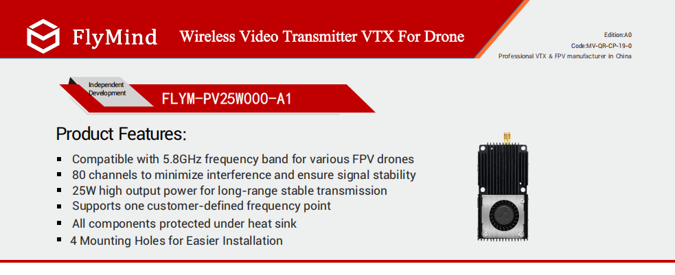 Check high-power VTX details
Field testing before batch use
A useful VTX test should not focus only on maximum distance. Instead, it should confirm whether the image stays predictable during the real inspection route. Repeated tests reveal turn loss, heat movement, channel noise, terrain shadow, and receiver-side weakness.
First, record a baseline in open space. Include flight distance, altitude, receiver height, antenna type, channel, weather, route direction, and visible image quality. This record makes later comparison more reliable.
Second, test the expected work scene. Open farmland, forest edge, hill route, industrial park, coastline, and urban-edge flight all create different signal conditions. Therefore, one clean field result should not represent every mission.
For operational planning, official guidance should also be checked. For example, the UK Civil Aviation Authority explains FPV flying requirements, including direct sight and observer considerations. This is why VTX selection should be considered together with route planning, receiver position, test records, and local compliance requirements.
Third, run a heat and vibration check. A short bench test proves only that the system powers on. However, a mission-level runtime test shows whether the module, connector, power supply, and cooling layout can support repeated use.
Recommended inspection test order
- Start with channel confirmation and receiver antenna inspection.
- Then test power input under throttle and payload load.
- Next, fly the same route at two safe altitudes to compare path loss.
- After that, repeat turns at the far end to check antenna shadow.
- Finally, record image quality after warm operation, not only at startup.
Procurement checklist for inspection drone VTX projects
A professional inquiry should include more than the required distance. The complete link includes aircraft type, video input, antenna location, receiver plan, power supply, environment, quantity, and customization needs. Therefore, a clear project file can reduce wrong matching and repeated sample changes.
For standard inspection routes, 5.8GHz 10W, 16W, and 25W should stay as the main selection path. Special 6–7GHz models can be discussed for crowded RF environments, city inspection, high-frequency anti-interference, OEM projects, and custom channel planning.
Meanwhile, 2.5W should remain a sample, entry-level, or small-frame auxiliary option. It can support short-distance layout checks, but it should not become the main product path for serious inspection routes.
FAQ
Which VTX power level fits inspection drones best?
It depends on the route. 25W fits demanding long-route inspection, 16W fits mixed industrial routes, and 10W fits compact platforms or validation builds. The final choice should also consider receiver height, antenna placement, power input, and cooling.
Does higher output always remove snow screen?
No. Higher output helps when distance, terrain loss, or low RF margin is the main issue. However, it cannot fully solve wrong channels, damaged antennas, voltage drop, poor grounding, or overheating.
Why does the image break only during turns?
During turns, the aircraft body may block the antenna path. In addition, antenna angle and polarization may change quickly. Better antenna placement, receiver diversity, and extra RF margin can reduce this problem.
When should 25W be selected?
25W makes sense for serious long-range routes, larger UAV platforms, open-area industrial missions, emergency monitoring, wide-area patrol, and high-value tasks where far-end image stability matters. The aircraft must also provide stable power, airflow, and secure antenna installation.
When is 16W better than 10W?
16W is better when the route includes light woodland, suburban areas, industrial parks, long corridor inspection, fixed-wing cruising, or mixed RF conditions. It gives stronger margin during turns, partial blockage, and medium-to-long distance work.
When is 10W enough for inspection drones?
10W is suitable when the route is mostly open, the aircraft is compact, and the inspection distance is short to medium. It is also useful for sample testing, training routes, equipment inspection, and controlled validation before higher-power deployment.
When should special 6–7GHz options be considered?
Special 6–7GHz options are mainly useful for OEM, city inspection, high-frequency anti-interference, or custom channel projects. They should be planned with receiver compatibility, antenna choice, compliance needs, and the final use environment.
Summary and inquiry checklist
In summary, inspection drone video stability should be treated as a complete link problem, not a single-part problem. First, identify whether the image shows gradual snow, nearby noise, turn-related loss, black screen, or full disconnection. Then, check antenna layout, receiver height, power wiring, heat control, and channel planning before final product matching.
For a stable FlyMind fpv video transmitter project, send the aircraft type, target distance, flight environment, frequency preference, receiving side, quantity, and OEM/ODM needs. These details help match 10W, 16W, or 25W more accurately.
- First, record the exact image symptom: snow screen, weak signal, jumping image, black screen, or disconnection.
- Second, match the power class: 10W for practical range, 16W for stronger mixed-scene margin, and 25W for serious long-range industrial work.
- Finally, confirm the complete link: antenna, receiver, power input, cooling, channel plan, quantity, and customization requirements.


Contact us
Name*
Tel
Mail*
Requst*