In FPV projects with several drones working in the same area, a stable video image is rarely decided by output power alone. A planned fpv vtx setup needs clean channel spacing, correct receiver matching, suitable antenna placement, stable power input, and enough thermal margin before the aircraft leaves the ground.
Therefore, channel planning should be treated as a flight preparation step, not a last minute field adjustment. This article explains how to use 80CH planning for 5.8GHz analog video links, how to avoid channel conflict in multi aircraft work, and how to match 10W, 16W, and 25W FlyMind options to real project conditions.
Start with the visible image problem
First, an unstable FPV image should be read as a system symptom. Snow screen, rolling image, nearby noise, weak far end picture, and sudden black screen often point to different causes. Because of this, channel planning should begin with the exact image behavior.
For example, snow that grows with distance usually suggests low RF margin, poor antenna direction, or route blockage. However, snow that appears near takeoff may come from channel conflict, receiver overload, dirty power, or a wrong frequency match. These two problems should not be solved in the same way.
Meanwhile, image breaks during turns often point to antenna shadow. Carbon plates, batteries, payload shells, landing gear, and metal brackets may block the RF path for a short moment. Therefore, antenna position should be tested on the final aircraft layout, not only on a bench.
Fast Channel Diagnosis Map
| Visible problem | Likely direction | Recommended check |
|---|---|---|
| Snow grows with distance | Low RF margin | Receiver height, antenna direction, power class, line of sight |
| Snow appears nearby | Power noise or channel conflict | Grounding, cable route, exact frequency match, receiver overload |
| Image breaks during turns | Antenna shadow | Antenna location, polarization, aircraft body blockage |
| Other aircraft image appears | Channel overlap | Main channel spacing, backup channel spacing, receiver lock |
| Sudden black screen | System interruption | Voltage drop, heat, camera output, loose SMA or JST connector |
Why channel conflict happens in multi aircraft work
First, channel conflict does not always mean two transmitters use the same channel. In real flight fields, adjacent channels can still disturb each other when spacing is too tight, power is high, or receivers are placed too close together. As a result, a channel may look correct on paper but still perform poorly in the field.
Secondly, different devices may use different channel labels. One receiver may show a band and channel name, while another device may show the real frequency point. Therefore, a professional channel plan should record the exact frequency, not only the channel number.
In addition, high power transmitters create a larger RF footprint around the launch area. A 10W, 16W, or 25W module can provide more useful margin at distance, but it can also overload a nearby receiver during ground preparation. For this reason, near field testing and route distance testing should be separated.
Finally, weak installation can make channel planning look worse than it is. Bad antenna placement, poor grounding, long lossy cables, unstable voltage, and heat buildup can all create image noise. In other words, 80CH planning works best when the full video link is built cleanly.
Build a practical 80CH channel map before field testing
First, list every aircraft, transmitter, receiver, antenna, and backup unit. A useful planning sheet should include aircraft number, main frequency, backup frequency, power level, receiver model, antenna type, and flight zone. This makes the setup easier to repeat during training, inspection, and batch delivery.
Next, separate main channels and backup channels. A backup channel should not sit near another active link, because it needs to solve interference rather than move the problem to a different point. Therefore, every backup frequency should be tested like a primary frequency.
Then, test one link at a time. Power on one aircraft, confirm receiver lock, record image quality, and power it down. After that, repeat the process for every unit. This method makes it easier to find a wrong channel, weak antenna, or noisy power line before the combined test.
Finally, activate all planned links together. This step reveals receiver overload, adjacent channel problems, antenna layout issues, and heat related instability. Consequently, the channel map becomes a tested operating rule instead of a simple document.

Recommended 80CH planning fields
For repeatable projects, the planning sheet should be simple enough for field use. It should not become a long engineering file that nobody checks before takeoff. Instead, it should answer the practical questions that decide whether the video system will stay predictable.
- Aircraft ID and mission zone.
- Main channel, real frequency, and backup frequency.
- VTX power class: 10W, 16W, or 25W.
- Receiver model, antenna type, and antenna height.
- Ground station spacing and receiver placement.
- Test result after all active links run together.
Match 10W, 16W, and 25W to the real mission
For normal 5.8GHz planning, 10W and 16W should carry the main product path. They support practical 80CH channel grouping, familiar analog receiver matching, and stable low latency FPV video transmission. At the same time, 25W should remain the high power option for serious long distance work.
However, power should not be selected by number alone. The better question is whether the aircraft has enough space, airflow, voltage stability, antenna clearance, and receiver support. A clean 10W plan can be more reliable than a poorly installed 25W setup.
10W 5.8GHz: balanced power for structured channel planning
First, 10W fits medium distance projects where the route is mostly open and the main risk is weak far end video. It is also suitable for multi aircraft training, farm mapping, campus patrol, site inspection, and open area industrial routes. Moreover, the 80CH layout supports cleaner channel separation before flight.
This power class works best when receiver height, antenna direction, power wiring, and cooling are already reasonable. Otherwise, avoidable installation losses may hide the actual benefit of the VTX. For this scenario, the 5.8GHz 10W 80CH drone VTX is the natural product match.

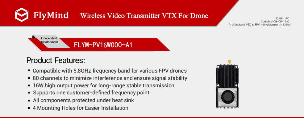
16W 5.8GHz: stronger margin for mixed environments
Next, 16W is useful when the route mixes distance, light blockage, and RF pressure. It suits industrial parks, suburban inspection, long corridor routes, rolling hills, larger multirotor platforms, and fixed wing cruise missions. In these scenes, extra signal margin helps protect the image during turns, climbs, and route changes.
At the same time, a stronger transmitter requires a cleaner receiver side plan. Ground receivers should not sit too close to an active high power transmitter during launch preparation. Therefore, the 5.8GHz 16W low latency VTX should be paired with documented channel spacing, antenna position, and heat testing.
25W 5.8GHz: high power option for serious long range work
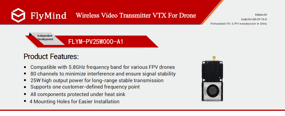
Finally, 25W should be considered when distance pressure is severe and the aircraft can support the installation requirements. It fits larger UAV platforms, open area industrial routes, emergency monitoring, wide area patrol, and long distance fixed wing work. However, it should not be used as a shortcut around poor channel planning.
Because the output is higher, thermal design becomes more important. The aircraft should provide stable voltage, secure mounting, airflow around the heat sink, and a reliable antenna connection. Otherwise, higher output may expose weak wiring, poor cooling, or connector vibration faster.
Installation and receiver checks that decide stability
Even a well planned channel map can fail when the antenna sits in the wrong place. The VTX antenna should stay away from carbon plates, batteries, metal mounts, ESC wires, and enclosed payload shells. A clear RF path often improves video stability more than a blind power increase.
At the same time, the receiver side should be included in every test. Low receiver height, poor antenna direction, wrong polarization, long cable loss, or receiver overload can make a strong airborne unit look weak. Therefore, the ground station setup should be documented together with the aircraft setup.
Cooling is another key detail. High power analog VTX modules create heat during long operation, especially when the aircraft is static, slow, or mounted inside a narrow compartment. Consequently, the heat sink should face airflow, and the module should not be sealed in foam, tape, or a closed pocket.

Installation checklist before flight
- First, connect a suitable antenna before powering the VTX.
- Next, keep the antenna away from carbon fiber, batteries, and metal plates.
- Also, separate video wiring from ESC and motor power lines.
- Then, check SMA connectors, coax cables, JST plugs, and solder joints under vibration.
- Finally, test cooling under realistic runtime, not only during a short bench check.
Testing before procurement and batch integration
A useful VTX test should not focus only on maximum distance. Instead, it should confirm whether the image stays predictable during the real mission route. Repeated tests reveal channel noise, turn loss, terrain shadow, heat movement, receiver side weakness, and connector vibration.
First, record a baseline in open space. Include flight distance, altitude, receiver height, antenna type, channel, weather, route direction, and visible image quality. This record makes later comparison more reliable.
Second, test the expected working scene. Open farmland, forest edge, hill route, industrial park, coastline, and urban edge flight all create different signal conditions. Therefore, one clean field result should not represent every mission.
Third, run a heat and vibration check. A short bench test proves only that the system powers on. However, a mission level runtime test shows whether the module, connector, power supply, antenna layout, and cooling path can support repeated use.
Recommended test order
- Start with channel confirmation and receiver antenna inspection.
- Then, test power input under throttle and payload load.
- Next, fly the same route at two safe altitudes to compare path loss.
- After that, repeat turns at the far end to check antenna shadow.
- Finally, record image quality after warm operation, not only at startup.
How to choose the right setup before sending an inquiry
Before product selection, define the aircraft type. Multirotor, fixed wing, VTOL, and industrial UAV platforms have different space, airflow, payload, and power limits. Therefore, the transmitter should match the airframe before output power is selected.
Next, define the target distance and environment. Open fields, hills, woodland, industrial parks, and city edge areas create different video link pressure. A 10W, 16W, or 25W option should follow the route difficulty instead of the highest number in the specification list.
In addition, confirm the receiver and antenna plan. The receiver must support the selected frequency range and channel list. The antenna should match the route shape, ground station position, and expected operating distance.
For special high frequency anti interference projects, 6-7GHz can be discussed separately. This may apply to city inspection, custom OEM frequency needs, and crowded RF areas. Nevertheless, the transmitter, receiver, antenna, and channel list must be planned as a complete system.
Simple selection logic
For medium distance 5.8GHz 80CH planning, start with 10W.
For longer routes or mixed environments, move to 16W.
For serious long range industrial work, consider 25W with stricter cooling and antenna checks.
For 6-7GHz anti interference needs, confirm receiver and antenna compatibility before sample testing.
FAQ
Summary and action steps
In summary, 80CH channel planning should happen before the field problem appears. First, identify whether the image problem is distance related snow, nearby noise, turn related image loss, receiver overload, or sudden black screen. Then, connect that symptom with channel spacing, receiver setup, antenna placement, power wiring, and heat control.
For a professional FlyMind fpv vtx project, 10W and 16W 5.8GHz modules should remain the main choices for normal 80CH planning. Meanwhile, 25W should support serious long range industrial routes, and 6-7GHz should stay in the special high frequency anti interference path.
- First, create a frequency based 80CH map with main and backup channels.
- Second, match 10W, 16W, or 25W to route distance, RF pressure, aircraft layout, and cooling ability.
- Finally, test one link at a time, then test all active links together before flight.
Inquiry CTA
Send project details for VTX channel planning
For accurate matching, send the aircraft type, target distance, flight environment, frequency preference, receiver setup, quantity, and OEM/ODM requirements. These details help FlyMind recommend a practical power class, channel plan, and product path before sample testing.
- Drone type: multirotor, fixed wing, VTOL, or industrial UAV platform.
- Target distance: medium route, long route, or strong distance project.
- Flight environment: open field, hills, woodland, industrial park, or city edge RF area.
- Frequency preference: standard 5.8GHz planning or special 6-7GHz anti interference planning.
- Receiver setup: receiver model, antenna type, ground station layout, and backup channel needs.
- Quantity and customization: sample test, batch project, OEM logo, ODM frequency, connector, or channel arrangement.


