VTX Power Selection Guide | EIRP & Link Budget for Industrial UAV Video Transmitters
Many system integrators select VTXs by simply chasing higher transmit power while ignoring Effective Isotropic Radiated Power (EIRP), link margin, heat dissipation and regulatory compliance. This article distinguishes between nominal power and actual radiation performance, provides VTX power selection guidelines for different operational scenarios, and helps engineers avoid various engineering pitfalls brought by high-power video transmitters.
Quick Navigation
Why Nominal VTX Power Alone Is Not EnoughBasic Concepts: Nominal Power vs EIRPLink Margin Calculation & Industry StandardsVTX Power Level Scenario Comparison TableMulti-Band VTX Power Matching Strategy (1.2G/2.4G/3.3G/5.8G/7.2G/8.5G)Power Consumption, Temperature Rise & Power Derating Risks of High-Power VTXPractical Selection Steps & Pitfall ChecklistFAQContact UsI. Why Nominal VTX Transmit Power Should Not Be the Only Criterion
During procurement for industrial UAV system integration and OEM projects, many purchasing and hardware engineers hold a common misconception: to achieve longer flight range and more stable video transmission, simply select a higher-power analog VTX. Most suppliers only advertise "10W, 16W, 25W high-power video transmitters", leading integrators to assume that power level is linearly proportional to transmission distance. However, numerous field tests and high-low temperature reliability tests show that most project failures stem from this misunderstanding.
The nominal transmit power of an analog VTX refers to RF output power at the module’s RF port, not the effective signal strength radiated through the air. A complete RF chain includes the VTX, feedline, connectors, antenna, receiving VRX, physical obstructions and electromagnetic interference, all of which jointly determine final transmission performance. Simply raising VTX power creates a chain of side effects: higher overall power draw, shortened battery life, severe module overheating, automatic power derating at high temperatures, excessive RF radiation, spectrum interference and radio compliance risks.
For domestic industrial UAV applications including power line inspection, mapping, security patrol, wildfire monitoring and PV farm inspection, project acceptance criteria usually require long-range transmission free of snow and dropouts, stable video during aggressive flight maneuvers, no automatic power reduction under extreme temperatures, and full compliance with radio regulations. Many projects deploy 25W high-power VTX, yet poor antenna matching and excessive feedline loss result in lower link margin than a properly tuned 10W VTX paired with a high-gain directional antenna.
For B2B buyers, the core goal of component selection is not "choosing the maximum power", but rather calculating sufficient link margin based on flight range, obstruction level, frequency band, onboard power supply and available heat dissipation space, while controlling cost, power consumption and thermal load to guarantee mass-production stability. This is why we focus heavily on link margin evaluation in this guide.
FlyMind Analog VTX series covers 5.8G power levels from 1.8W/2.5W/5W/10W/16W up to 25W. The 10W version supports multiple frequency bands: 1.2G, 2.4G, 3.3G, 5.8G, 7.2G and 8.5G. We deliver customized analog video transmission solutions tailored to different operating conditions. Our team matches power and band combinations via link budgeting at the selection stage to avoid engineering risks caused by over-specifying high power.
II. Nominal Power vs EIRP: Key Distinctions for RF Engineers
2.1 VTX Nominal Transmit Power (Pout, dBm)
Nominal transmit power is the RF power measured at the VTX SMA output port under standard supply voltage, 25°C ambient temperature and specified frequency points. Units are typically Watts or dBm. Industry conversion reference: 1W=30dBm, 2.5W≈34dBm, 5W≈37dBm, 10W≈40dBm, 16W≈42dBm, 25W≈44dBm.
A common pitfall: many low-cost VTXs advertise peak power instead of continuous rated output power. Peak power cannot be sustained during continuous operation or high-temperature conditions; power quickly drops off, creating a large performance gap between bench testing and field flight. Industrial-grade VTXs must be evaluated on continuous rated RF output, not instantaneous peak power. All power ratings on FlyMind analog VTXs refer to continuous rated RF output. Every unit undergoes burn-in and high-low temperature power calibration before delivery to ensure consistent batch performance.
2.2 EIRP (Effective Isotropic Radiated Power)
EIRP is the most critical metric for wireless link planning and radio regulatory compliance. Formula:
EIRP(dBm) = VTX Output Power (dBm) + Transmit Antenna Gain (dBi) − Total Feedline & Connector Loss (dB)
EIRP represents the equivalent power radiated toward the target direction as if transmitted from an ideal isotropic antenna. The same 10W VTX will produce drastically different EIRP when paired with a 2dBi omnidirectional mushroom antenna versus a 12dBi directional patch antenna. Long or poor-quality RF cables introduce significant feedline loss and further reduce EIRP. Radio authorities and export certification (FCC/CE) regulate EIRP rather than raw VTX module power.
Engineering example: 5.8G 10W analog VTX (40dBm), 1dB loss from SMA jumper cable, paired with an 8dBi directional antenna. EIRP=40+8−1=47dBm. If replaced with a 2dBi omnidirectional antenna, EIRP=40+2−1=41dBm — a 6dB difference that directly reduces effective transmission range in line-of-sight open areas. This case clearly demonstrates that antenna and feedline selection often have a greater impact on link performance than upgrading VTX power levels.
III. Link Margin Calculation & Industry Engineering Standards
Link margin is the surplus signal level (in dB) above receiver sensitivity after accounting for all losses across the entire wireless link. This margin acts as a buffer against environmental changes: drone attitude shifts, antenna blockage, foliage attenuation, sudden electromagnetic interference, rain/fog fading, and minor power drop caused by battery voltage sag.
Full link budget formula:
Link Margin = VTX Power + Transmit Antenna Gain + Receive Antenna Gain − Total Feedline Loss − Free Space Loss − Environmental Attenuation − Receiver Sensitivity
Universal engineering margin standards:
- Open line-of-sight, unobstructed, low-interference environment: ≥10dB margin;
- Suburban terrain with scattered trees, mild obstructions: ≥15dB margin;
- Mountainous woodland, urban industrial zones, high-interference complex environments: ≥20dB margin;
- Margin below 6dB: Extremely fragile link; minor blockage or turning will trigger video snow and transmission dropouts.
A frequent mistake made by procurement engineers: relying solely on the vendor’s advertised maximum range without performing link budgeting. All "maximum transmission distance" claims are measured under ideal open line-of-sight conditions with high-gain antennas and zero interference. Effective range shrinks drastically under real-world operating conditions. Therefore, the first step in component selection is not choosing power, but collecting project parameters: maximum flight distance, terrain, foliage/mountain obstructions, nearby Wi-Fi base stations, planned frequency band, antenna layout, and VRX receiver sensitivity.
When supporting integrators with VTX solution design, FlyMind engineers complete link budget evaluations based on flight route and antenna schemes. We help clients decide whether to increase VTX power or optimize antenna/feedline first, striking the optimal balance between cost and performance.
IV. VTX Power Level Scenario Comparison Table
FlyMind analog VTX covers power levels: 1.8W, 2.5W, 5W, 10W, 16W and 25W, suitable for lightweight multirotor, medium VTOL, large fixed-wing and security patrol UAV platforms. The table below summarizes applicable scenarios, power draw, thermal requirements and project types for each power grade to speed up B2B procurement decisions.
| VTX Power Level | Typical Application Scenarios | Key Advantages | Limitations & Risks |
|---|---|---|---|
| 1.8W / 2.5W (5.8G) | Lightweight FPV, small multirotor UAVs, indoor inspection, short-range factory patrol, educational training drones | Ultra-low power consumption, negligible heat generation; no extra heat sink required, minimal payload weight; low interference for multi-drone swarm operations | Only suitable for short-range line-of-sight flight; insufficient margin for woodland/mountain obstructions; not recommended for long-distance projects |
| 5W (5.8G) | Conventional PV farm inspection, farmland mapping, suburban open-area patrol, medium VTOL UAVs | Balanced power draw and thermal output; simple heat dissipation structure; mature mass production and high cost performance | Insufficient link margin for heavy woodland obstructions and long-range fixed-wing missions; poor performance in high-electromagnetic-interference environments |
| 10W (Multi-band options: 1.2G/2.4G/3.3G/5.8G/7.2G/8.5G) | Workhorse unit for industrial inspection missions; mild woodland obstructions, medium-long range fixed-wing flight, multi-drone cluster operations; the most widely adopted power grade among system integrators | Rich band selection balancing range, penetration and anti-interference; proven thermal design; support for OEM channel customization; best overall performance balance | Basic thermal conduction required; prolonged static full-power operation without heat dissipation is not recommended; low-band versions come with larger antenna dimensions |
| 16W (5.8G) | Mountain patrol, forest edge surveillance, long-distance river inspection, medium fixed-wing UAVs; projects requiring extra margin without jumping straight to 25W | Ample link margin with lower power consumption and heat generation than 25W models; reduced thermal design difficulty; the optimal compromise solution | Higher operating current requiring stable BEC power supply; reserved onboard space for heat dissipation is mandatory |
| 25W (5.8G) | Long-range fixed-wing UAVs, coastal patrol, heavy woodland obstructions, beyond visual line-of-sight security missions, large industrial UAV special projects | Abundant RF power reserve; strong margin advantage under heavy obstruction and multipath interference; built for extreme operating conditions | Extremely high heat output requiring professional active cooling; increased overall power draw reduces flight endurance; strict RF radiation control necessitates thorough regulatory compliance assessment |
Field project data shows that over 70% of conventional inspection projects by domestic industrial UAV integrators select the 10W multi-band VTX as the primary choice. Operators can switch frequency bands to mitigate on-site interference without unnecessarily upgrading to 16W or 25W. Only upgrade power levels when link budgeting clearly proves insufficient margin.
V. Multi-Band VTX Power Matching Strategy (1.2G/2.4G/3.3G/5.8G/7.2G/8.5G)
Power level and frequency band must be selected together. Even with identical 10W output power, different frequency bands deliver vastly different penetration, free-space loss and anti-interference performance. The FlyMind 10W analog VTX supports 1.2G, 2.4G, 3.3G, 5.8G, 7.2G and 8.5G bands to match diverse field conditions — this is why complex projects prefer this model.
5.1 5.8GHz 10W VTX
5.8G is the most mainstream analog video transmission band, featuring compact antenna size, abundant channels and mature VRX receiver hardware. The main downside is spectrum congestion; heavy Wi-Fi and wireless equipment interference is common in urban areas, factory compounds and substations. The 5.8G 10W VTX delivers the best cost-performance for open farmland and PV inspection sites with clean electromagnetic environments. If severe interference exists, raising power will not resolve co-channel noise; switch frequency bands first.

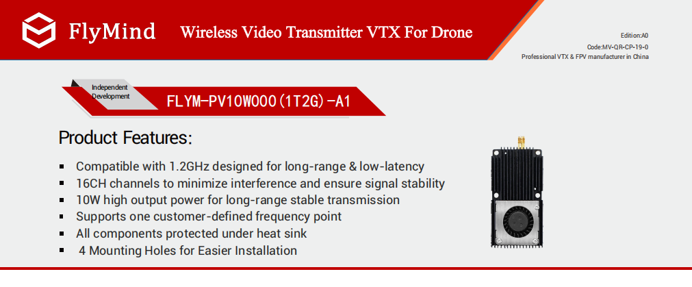
5.2 1.2GHz 10W VTX
This low band offers superior diffraction and foliage penetration, making it ideal for mountainous and wooded terrain. Free-space path loss is far lower than 5.8G at equal distances. The main drawbacks are larger antenna size and fewer available channels; confirm local radio spectrum regulations before deployment. Best suited for wildfire monitoring, mountain mapping and long-range fixed-wing UAV missions.
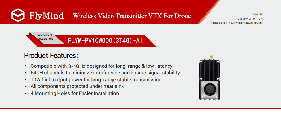
5.3 3.3GHz 10W VTX
This is an industrial-exclusive band with minimal Wi-Fi interference. It balances signal penetration and antenna footprint, making it the top choice for factory, substation and mine inspection projects. 7.2G suffers less interference than 5.8G but higher free-space loss; it is better for medium-range fixed-point inspection under severe electromagnetic noise.
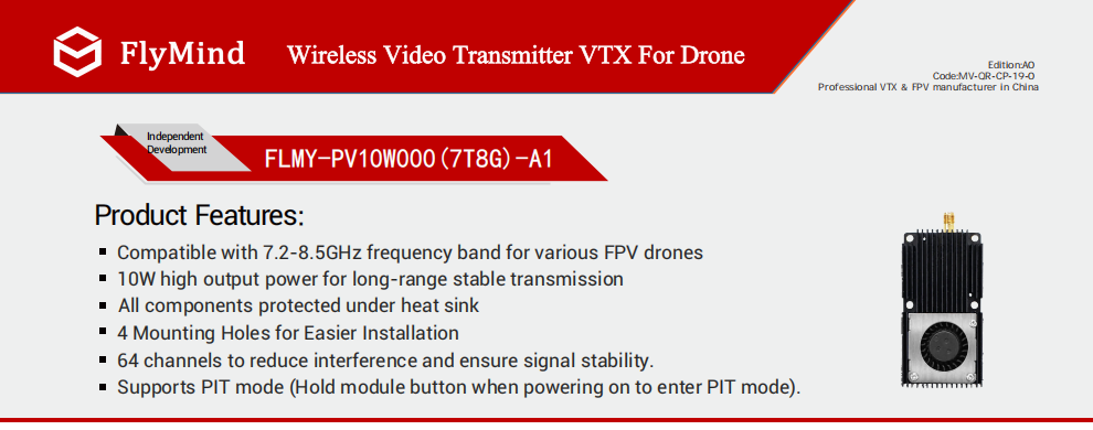
5.4 8.5GHz 10W VTX
This high-frequency band allows extremely compact antennas, perfect for UAVs with strict onboard space and antenna size limits. However, path loss is high and penetration is weak; only suitable for short-range unobstructed flights requiring strict electromagnetic isolation.
Band selection summary: When facing heavy interference or physical obstructions, prioritize low-frequency or industrial exclusive bands (1.2G, 3.3G, 7.2G) instead of upgrading a 5.8G VTX from 10W to 25W. Raising transmit power only elevates the noise floor under co-channel interference and cannot eliminate video snow.
VI. Power Draw, Temperature Rise & Power Derating Risks of High-Power VTX
Higher VTX power directly increases power consumption and heat generation in RF power amplifiers — this is the most common integration pitfall for analog video transmission systems. Many modules run stably at full power during 25°C bench testing, yet internal temperature rises sharply inside sealed airframes during summer outdoor flight. The built-in over-temperature protection triggers automatic power derating, shrinking link margin and causing random video dropouts during field flights.
Power consumption reference (12V nominal supply):
- 2.5W VTX: Total current ~0.8~1A; minimal heat; no extra heat sink required;
- 5W VTX: Total current ~1.2~1.6A; thermal pad mounting is sufficient;
- 10W VTX: Total current ~2.2~2.8A; thermal pad + chassis heat dissipation required; airflow must be reserved inside sealed compartments;
- 16W VTX: Total current ~3.5~4.2A; robust thermal conduction structure is mandatory; fully sealed installation is not recommended;
- 25W VTX: Total current ~5~6A; massive heat output requiring active forced cooling; prioritize airflow generated by propeller wash;
Always evaluate thermal conditions at the selection stage: whether the airframe is sealed, if propeller airflow is available, and maximum ambient operating temperature. For sealed fuselages and high-temperature regions, select the next lower power grade paired with higher-gain antennas instead of forcing a 25W solution.
Power supply stability also directly affects actual output power. Voltage sag from depleted batteries and high ripple on BEC regulators will cause VTX output power to drop. High-power models such as the 25W VTX require an independent power supply circuit and cannot share the same regulator with flight controllers and cameras.
VII. Practical Selection Steps & Pitfall Avoidance Checklist
- Collect project parameters: maximum flight range, terrain (open/woodland/urban), local electromagnetic environment, maximum operating temperature, airframe structure (sealed/ventilated), and antenna installation layout;
- Select frequency band first: assess interference conditions and decide between 5.8G and low/special bands (1.2G/3.3G/7.2G);
- Complete link budgeting to calculate required link margin; optimize antenna gain first before upgrading VTX power;
- Verify onboard power supply and heat dissipation space to evaluate power consumption and thermal costs of high-power hardware;
- Calculate EIRP to ensure compliance with domestic radio regulations and export FCC/CE standards;
- Conduct sample validation: high-low temperature burn-in and field flight tests to verify power retention under high temperatures and real-world link stability;
- Lock specifications for mass production, including channel table, power level and firmware version; support OEM customization.
Key Pitfall Summary:
❌ Never base selection purely on the vendor’s advertised "maximum transmission range";
❌ Do not attempt to resolve co-channel interference simply by raising VTX power;
❌ Never power on high-power VTXs without an antenna connected — this will burn out the power amplifier;
❌ Do not overlook feedline and connector losses; thin high-frequency cables introduce substantial signal attenuation;
✅ Follow this priority: complete link budget → optimize antenna performance → match VTX power level;
✅ For heavy obstruction and high-interference scenarios, switch to low-frequency or industrial exclusive bands instead of increasing power;
✅ For sealed high-temperature airframes, select conservative power grades and reserve extra thermal margin.
FAQ
Q1: With the same 10W VTX, how much range difference exists between 5.8G and 1.2G?
The gap is relatively small under open line-of-sight conditions. In foliage and mountain-obstructed environments, the 1.2G band delivers far stronger diffraction and longer effective range at equal power. However, 1.2G requires larger antennas and has fewer available channels; confirm spectrum licensing requirements before deployment.
Q2: What is the optimal link margin? Is more margin always better?
Only provision enough margin to meet operational requirements. Excessively high margin means over-specifying VTX power, bringing unnecessary heat, power draw and regulatory risks. 10~15dB margin suffices for open areas; 15~20dB is recommended for complex woodland missions. Margin exceeding 25dB represents unnecessary power redundancy.
Q3: Will a 10W VTX paired with a high-gain antenna exceed EIRP limits?
Yes. EIRP equals module power plus antenna gain minus feedline loss; higher antenna gain directly raises EIRP. We can help you calculate EIRP and provide power-locked firmware versions to meet regulatory limits if required.
Q4: Is a 25W VTX always more stable than a 10W unit?
No. Insufficient heat dissipation will cause continuous power derating on the 25W model under high temperatures. Power increases cannot resolve co-channel noise interference. Multiple field tests confirm that a well-tuned 10W VTX + high-gain directional antenna setup often delivers better stability than a poorly cooled 25W VTX.
Q5: Can your 10W multi-band VTX support OEM customization of channel tables and power limits?
Yes. FlyMind analog VTX supports custom channel mapping, power level locking, and SmartAudio/Tramp protocol adaptation. We provide ODM firmware tuning for UAV system integrators to adjust parameters according to project requirements.
Contact Us
FlyMind specializes in the R&D and manufacturing of industrial UAV analog VTX video transmitters. Our product lineup covers 5.8G power grades: 1.8W/2.5W/5W/10W/16W/25W. The 10W model supports 1.2G, 2.4G, 3.3G, 5.8G, 7.2G and 8.5G frequency bands. We provide sample testing, link budget evaluation and OEM/ODM customization for industrial UAV system integrators and OEM manufacturers.
If you are developing inspection, mapping or security UAV projects and need to select the correct analog video transmitter power grade, or require RF engineering support for link margin budgeting and EIRP compliance calculation, please get in touch to discuss your solution.
We provide datasheets, engineering samples and test reports, with mass-volume delivery and custom firmware development available.


Contact us
Name*
Tel
Mail*
Requst*